The Electronics of Early 3D Printers

If you make a purchase using a shopping link on our site, we may earn a commission. Learn More
In the first few years of hobby 3D printing, nothing was as neatly packaged as what we have today. I’ve covered aspects of this with the physical machine designs and the quality of filament, but the electronics may truly have been one of the least polished parts of early 3D printers.
Before the days of custom motherboards and nicely enclosed casings, almost every 3D printer used the same processor and associated electronics board—the Arduino Mega and RAMPS board. These weren’t unreasonable choices, especially given the grassroots nature of early 3D printers. But they did introduce some complexity and problems that I’m glad we don’t have to deal with anymore.
The Arduino was (and is) a well-known microprocessor that was affordable and easy to use for hobby projects. To use it as a 3D printer controller, you’d have to attach it to a computer via USB and use the free Arduino IDE software to upload firmware to the processor. Interestingly, the firmware we were using back then really isn’t too different than what is being used today—the Marlin project was popular in the early days, and many 3D printers still use a variant of it, although modern machines are starting to use more advanced firmware such as Klipper.
But even if the old firmware was technically the same code as what we’re using today, the way you interacted with it was much different. Since every 3D printer design was slightly different and everyone was constantly upgrading their machine to take advantage of the latest improvements, you often had to edit a configuration file and re-upload it to the Arduino to enable some new setting or adjust a calibration value. That’s right—some of the calibration required manually editing configuration files and uploading them to the printer over USB. This is part of why calibration sometimes took weeks, rather than minutes.
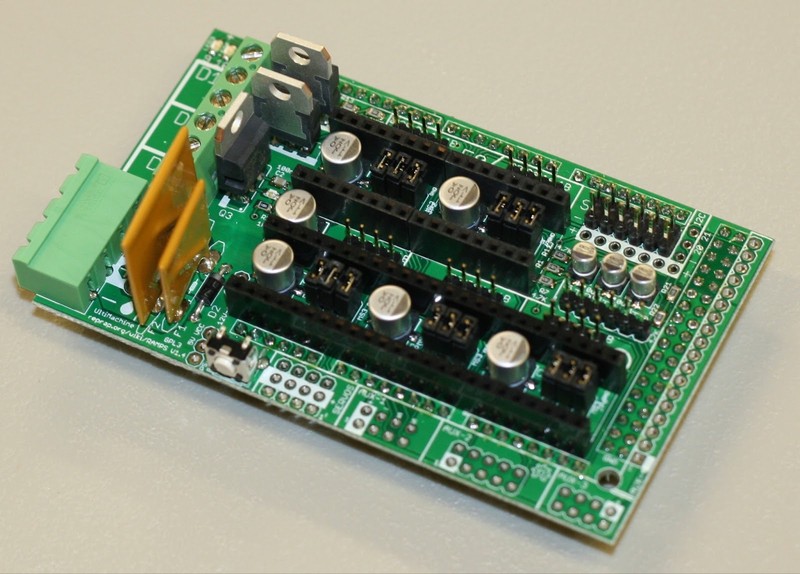
On the hardware side, most of the functionality was provided by the RAMPS board, which plugged into the Arduino Mega as an expansion board. The RAMPS had slots for 4 or 5 stepper motor drivers, which pressed into the board and enabled use of the stepper motors that moved the printer gantry, bed, and extruder. The RAMPS board also had various inputs and outputs to handle the rest of the printer’s needs, such as endstop sensors, the hot end thermistor and power.
Despite the RAMPS board being more-or-less the key enabling piece of early 3D printers, I don’t miss it. The system had some major annoyances and problems:
- Because the stepper motor drivers were swappable and every printer used slightly different motors, you had to tune the current on each stepper driver by turning a small screw. Too much current and the board would overheat, but the motor wouldn’t spin without sufficient current. This was a pain.
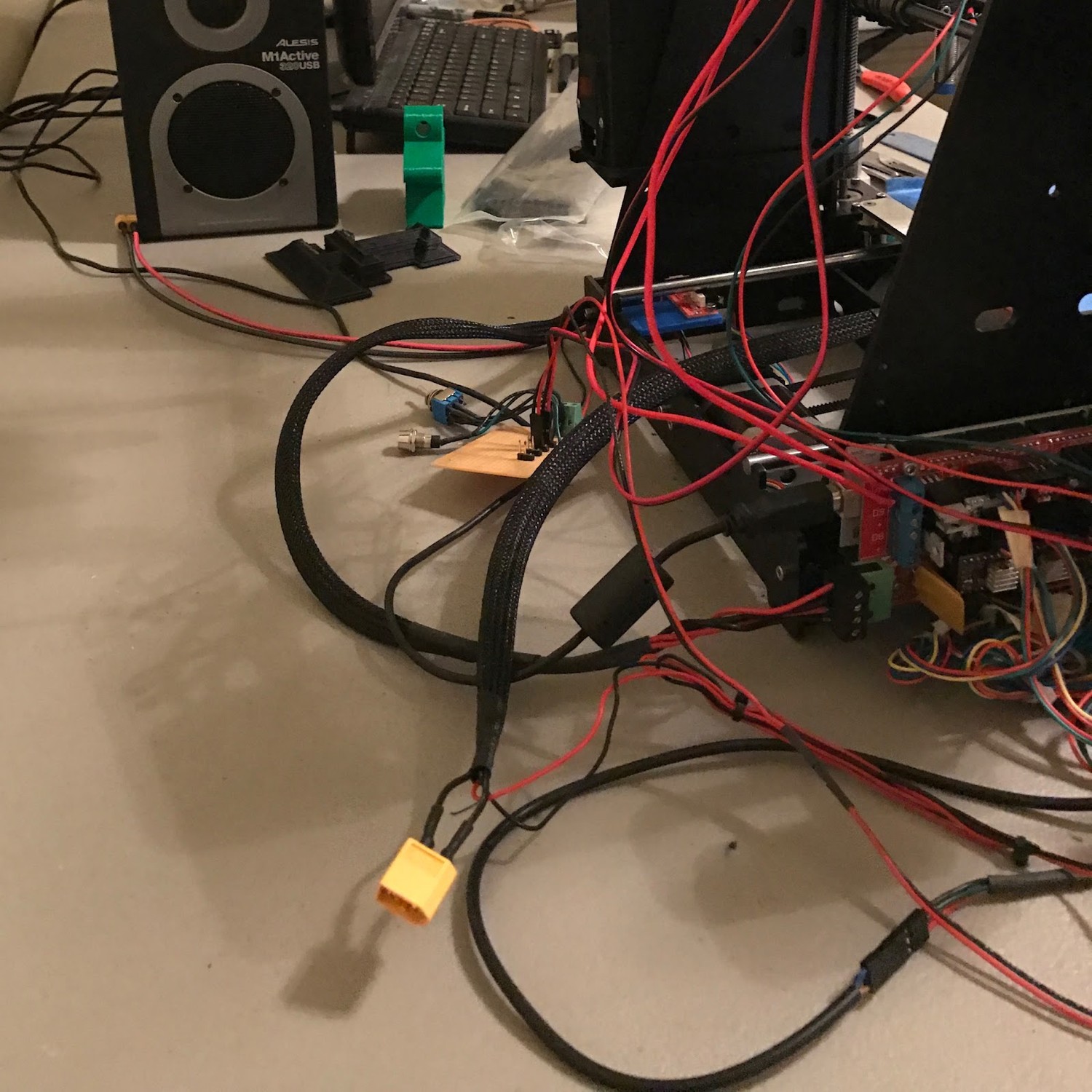
- Installing any upgrade required you to identify an appropriate set of pins on the RAMPS board and configure the firmware to use those pins for the desired function. Want to add an auto level bed probe? No problem, the firmware supports it, but you’ll need to look at a schematic to figure out which pins you can use, wire a custom connector, and carefully route the wires through the printer. Make sure you plugged the connector into the right pins and used those same pins in the config file! Otherwise, at best it won’t work, and at worst you just shorted something out.
- By far the biggest issue was the way the RAMPS board handled power. 3D printers use a lot of power for the heat bed and hot end, and all of the early machines had all of this power running through the RAMPS board itself. 12V power would come into the board through a set of screw terminals, and a set of MOSFET drivers would send it through more screw terminals to the heat bed and hotend. This could easily be 10-15 amps of current and was way beyond what should have been running through a small printed circuit board and simple screw terminals.
Of these issues, the power problems bothered me most, and while I didn’t really hear many stories of 3D printers catching on fire, I had at least one instance where a loose connection in one of the RAMPS screw terminals caused the terminal to melt and burned the edge of the board. That was enough for me to want to upgrade to a more robust solution, and like everything in early 3D printing, that meant doing something custom.
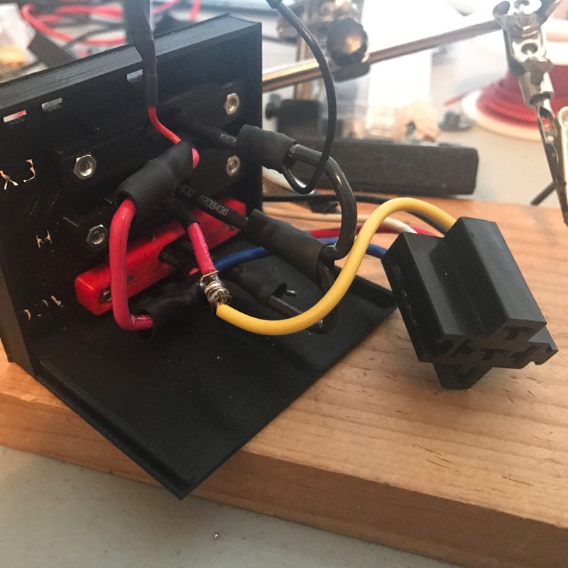
My approach to the problem was to buy a 12V automotive relay and rewire the printer electronics to switch that relay, which directly connected the heat bed to the 12V power supply running the printer. I first used a screw terminal strip with spade connectors to handle the power, and later switched to high-current XT60 connectors. This is actually the same direction most modern printers have taken, although they’ve taken the further step of using 24V power for the heatbed, which reduces current and has the side effect of decreasing heating time. Most modern printers also use solid-state relays, which don’t produce the constant clicking sound that my old solution did.
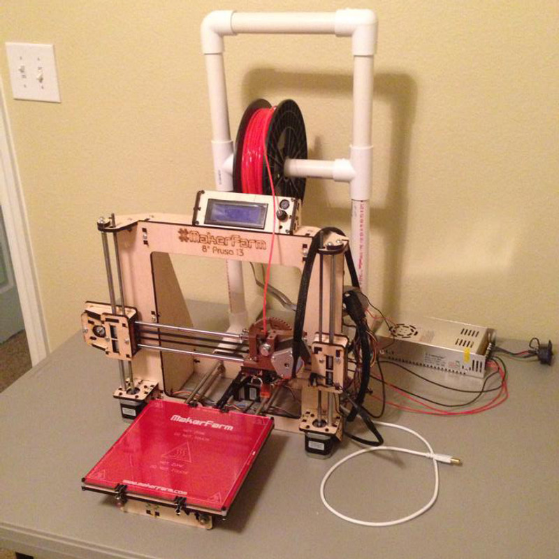
This wasn’t the only dubious part of early printers—the power supply most of us were using required you to wire your own 120V plug adapter, and typically you’d end up printing a plastic cover for the power supply to enclose the 120V wiring. But how do you get set up to print that first cover? Set the 120V wiring on your desk and hope for the best, obviously.
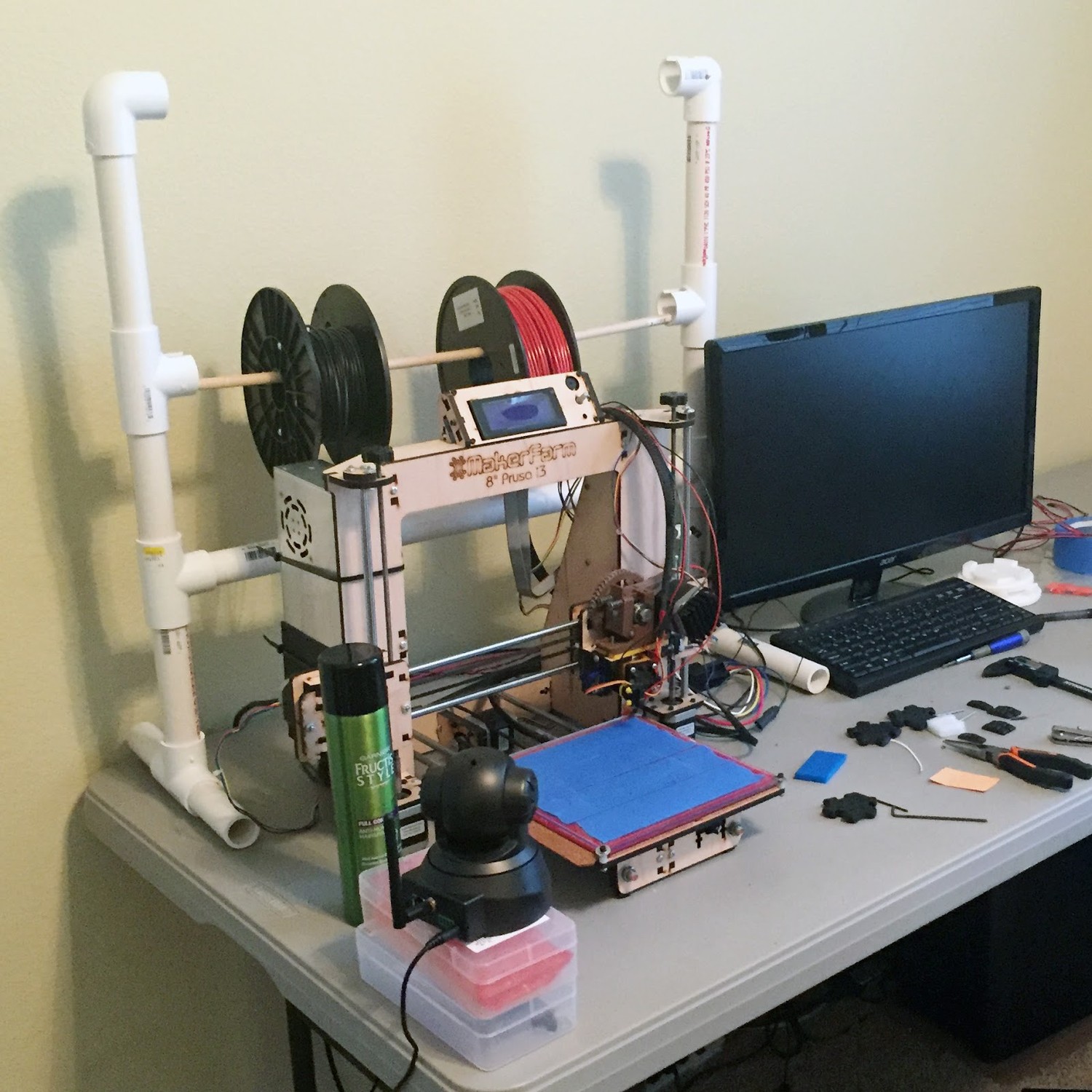
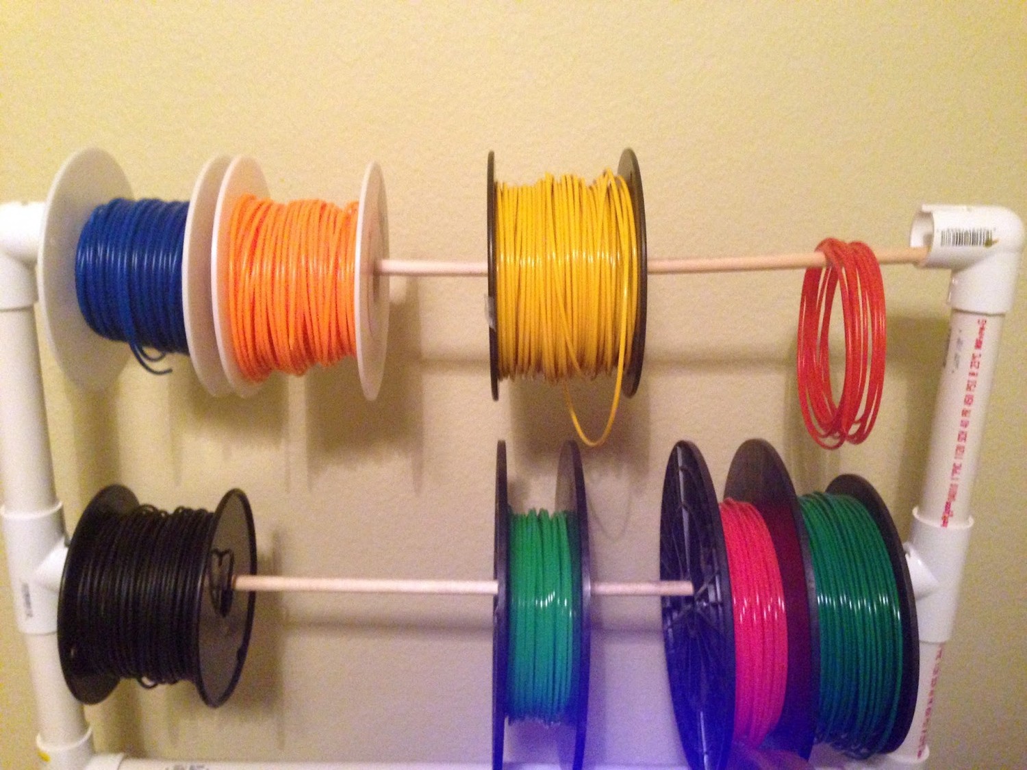
There were pros and cons to the way printers were built in those days. Everything was very custom, which opened up a world of possibilities for upgrades and improvements. A lot of the features we enjoy on modern 3D printers got their start from hobbyists plugging wires haphazardly into an Arduino and seeing what worked and what didn’t. But it was undoubtedly a less user-friendly time to be into 3D printing, and we all took on a bit of risk by working with mostly-unregulated electronics designs. There was also an absolute rat’s nest of wires, as you can see in the pictures. I don’t miss those parts of it.
Next time you open up a 3D printer to install an upgrade or check a board version number, pay attention to what you see inside—the labeled plugs, carefully routed wire bundles, and metal enclosures shielding the electronics. None of that happened overnight, and it wasn’t always that way, but it’s something to appreciate now.
Read more from the History of 3D Printing series
Origin Story: My Wooden 3D Printer
May 27, 2024
June 10, 2024