If you make a purchase using a shopping link on our site, we may earn a commission. Learn More
Sovol SV06 Plus Assembly Guide

Published: 2024-03-08
This guide will give you an idea what to expect when first opening and assembling the SV06 Plus.
Packaging
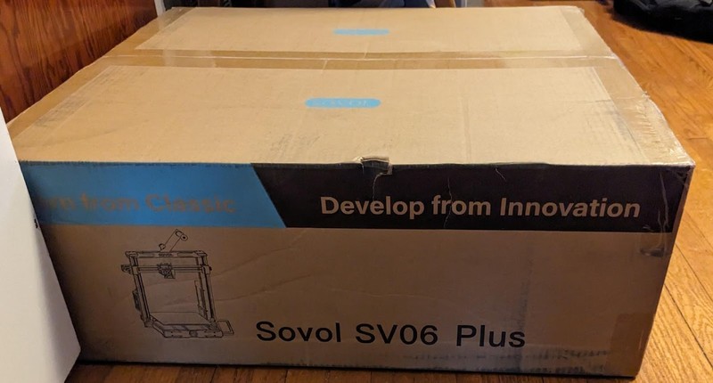
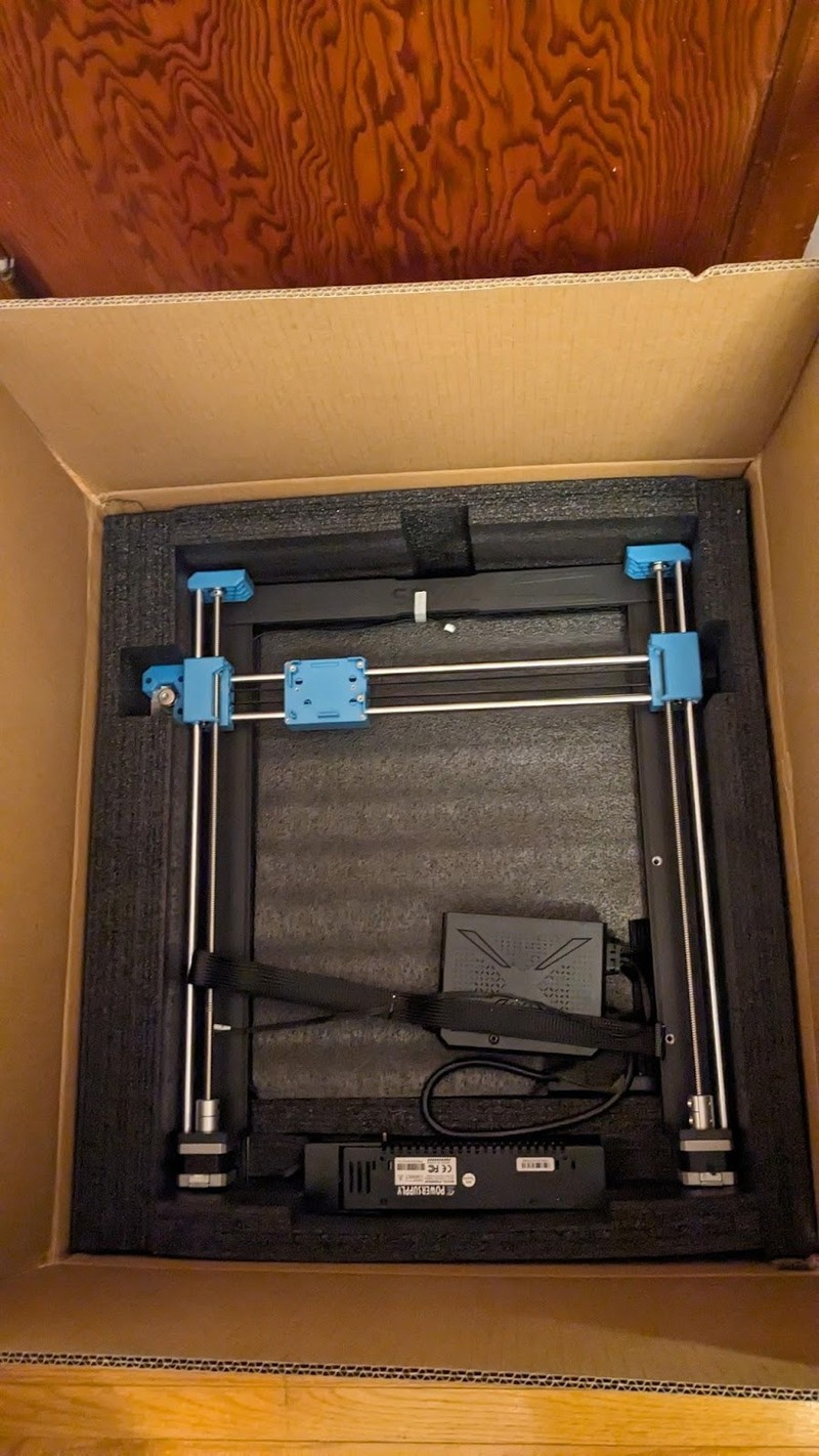
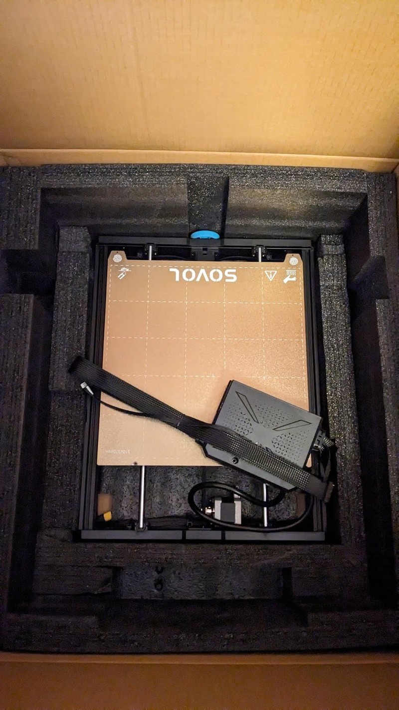
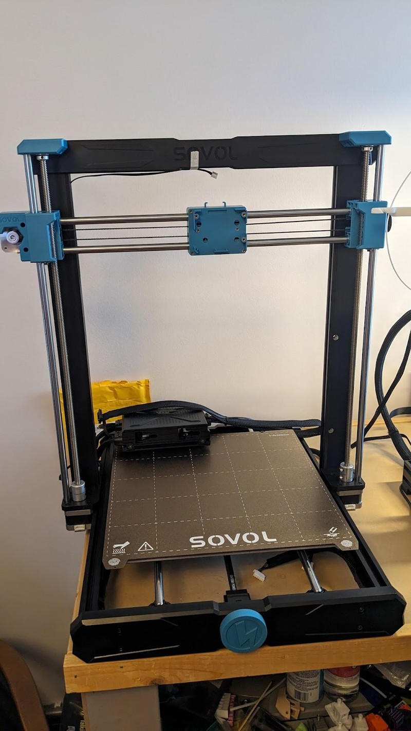
The SV06 Plus arrived in a very large, heavy box. Inside, very thick foam kept all the components well-protected. The printer can be considered partially assembled, and although it is not as assembled as a typical new Creality printer, its unusual design makes assembly easy.
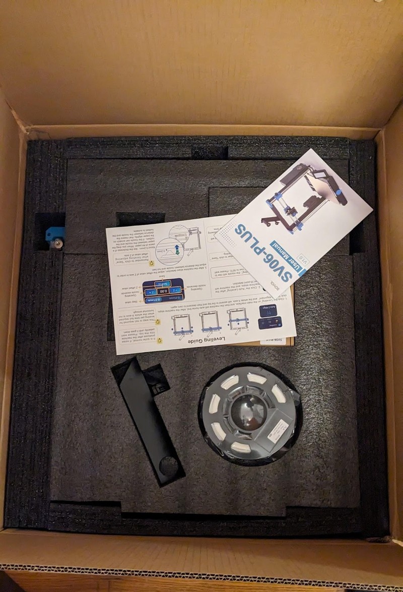
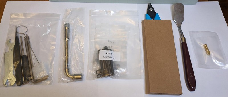
- spare brass 0.4mm nozzle
- rounded edge palette knife (for gently prying parts off the print bed if necessary)
- flush cut nippers
- angled nozzle socket wrench
- hex keys
- wrenches
- tweezers
- flathead screwdriver
- nozzle needle
- extruder push rod (heavy gauge blunted rod for clearing extruder from above)
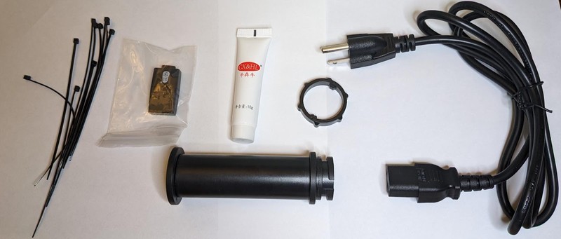
- 10 cable ties
- grease
- USB microSD card reader with a microSD card inserted
- spool holder
- spool holder locking ring
- power cord
This is a generous assortment and some of these accessories are higher quality than other 3D printers.
Assembly
While it is slightly less assembled than competing printers, there still isn’t much to do and assembly is easy, taking about 20-30 minutes. On Ender-style printers, the mainboard and power supply are mounted preinstalled on the underside. On the SV06 Plus, the mainboard and power supply boxes are separate and the user mounts these on each side of the printer. The mainboard is all prewired though and only a few connections need to be made, simplified by the fact that there are no limit switches to connect since the printer uses sensorless homing. In another unusual arrangement, the extruder is not mounted to the X axis.
To assemble the printer, the well-written, well-illustrated, clear manual instructs you to:
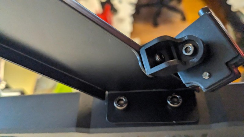
- Install the gantry into the base frame using long bolts driven in from the side. This is easy since you don’t have to access the underside of the printer. The aluminum extrusions of the base and gantry are machined so that the gantry slides smoothly and securely into pockets on the frame. The gantry drops to a perfect level and stays in place while you drive the bolts tight. These are large, long bolts which hold the gantry very firmly.
- Install the power supply using bolts through holes on the right side of the gantry. It was a little more difficult to get the bolt holes to line up at first since they’re inset into the gantry frame and the threaded holes in the power supply are small, but once in place the power supply is held in well.

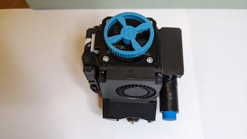
Install the extruder onto the X axis carriage. This was tricky since the screws are small and the extruder does not stay in place on its own. You have to hold the extruder on the carriage with one hand and thread the screw with the hex key with the other hand. Once you get the first screw in, the rest are easy.
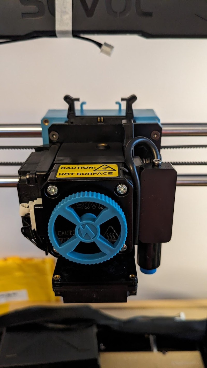
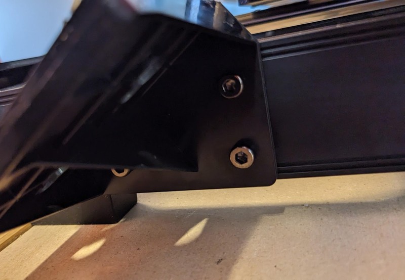
Attach the extruder to the gantry using the provided screws 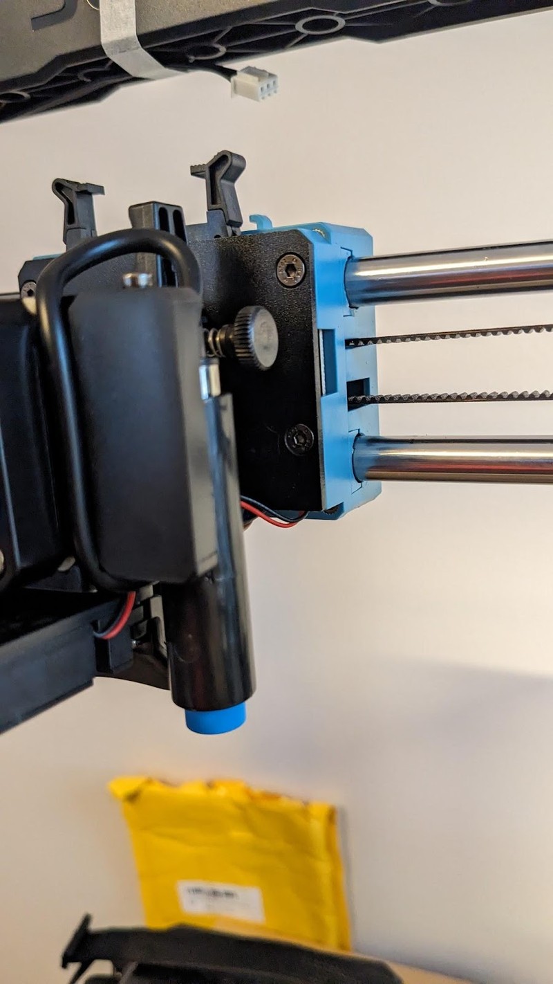
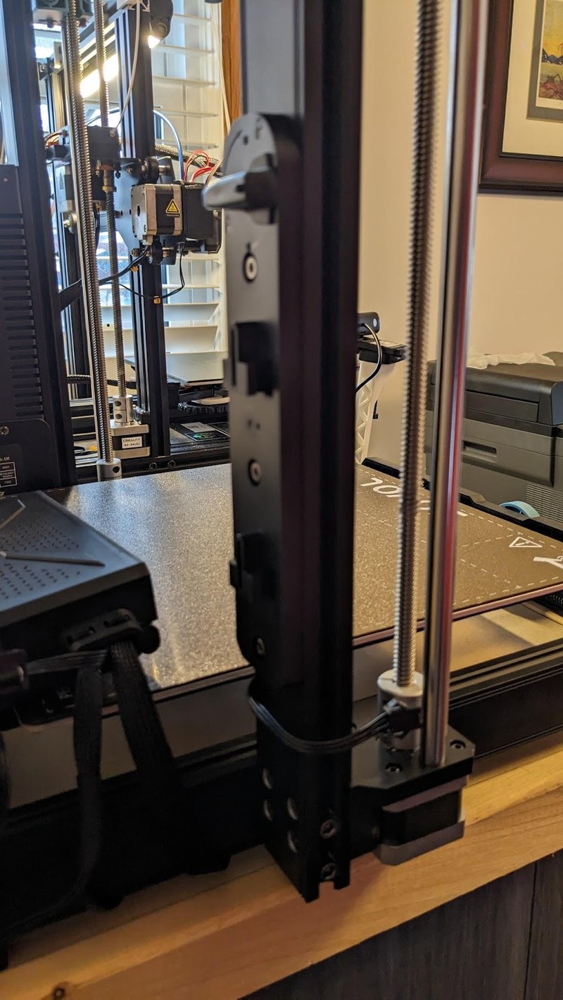
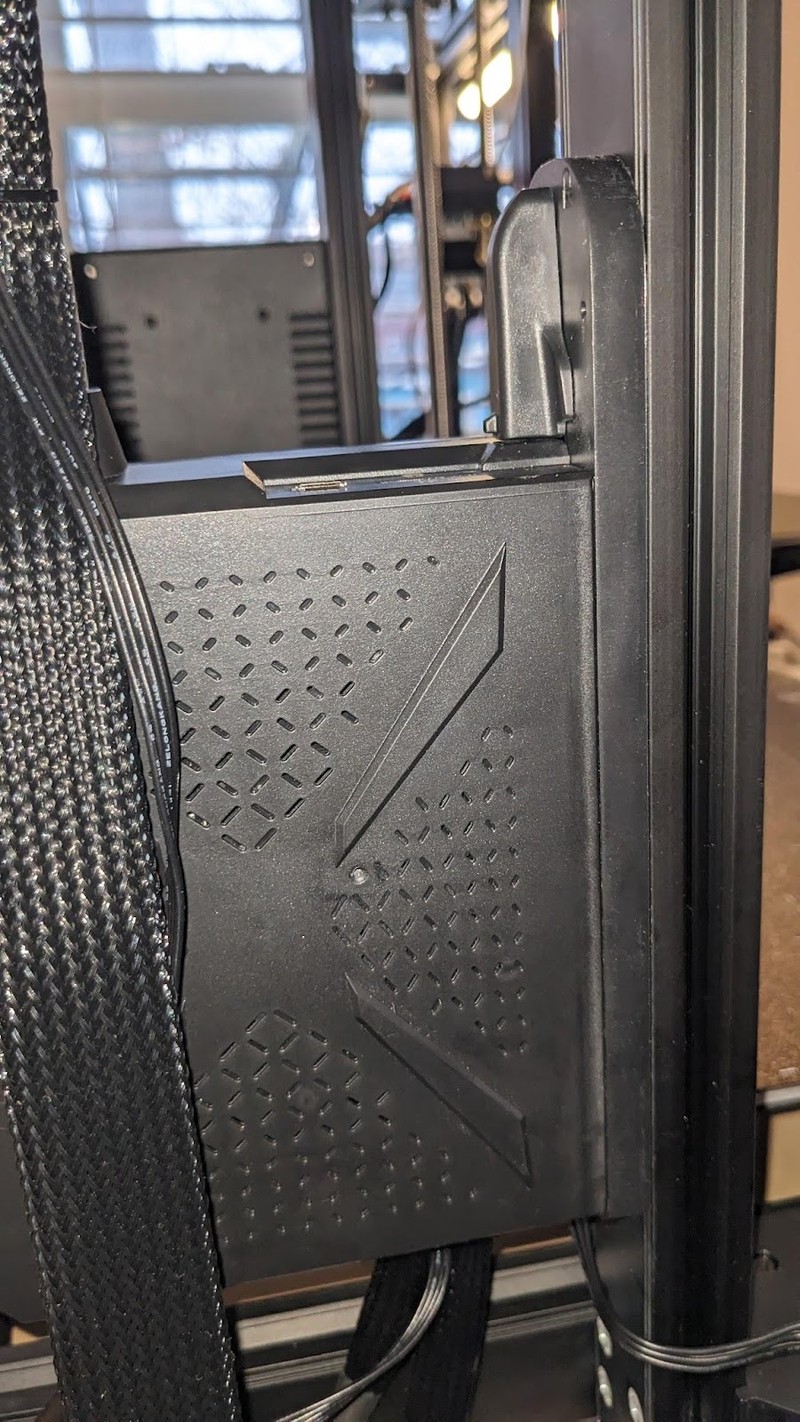
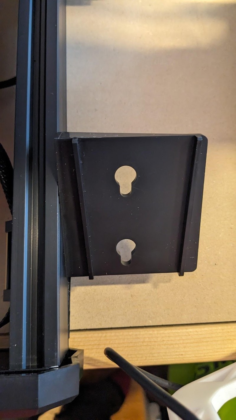
Slot the mainboard box onto the tabbed plastic bracket on the frame and lock it into place by turning the “aircraft switch” 90 degrees.
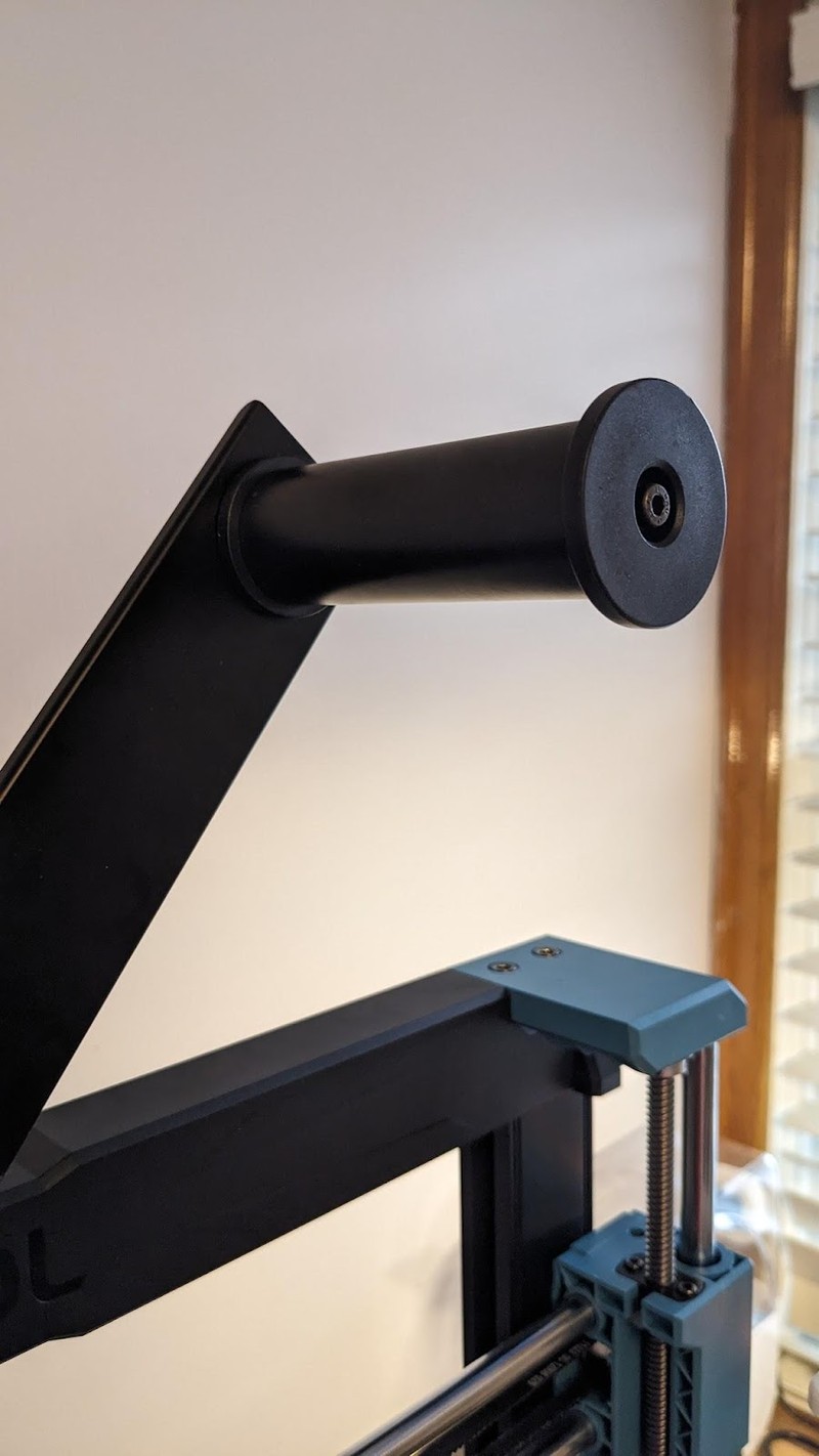
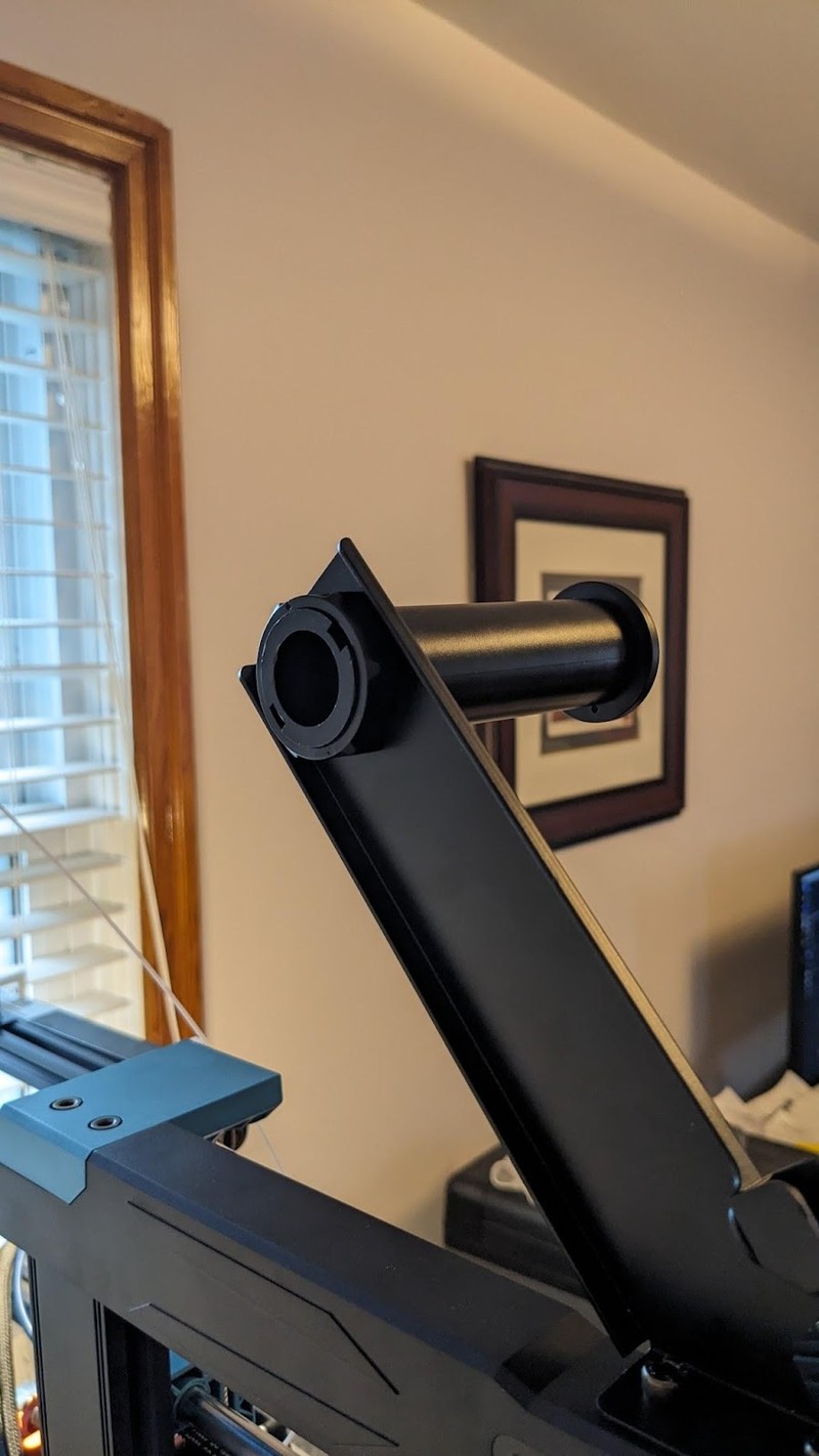
- Install the filament holder bracket onto the top of the frame. Place the filament holder into the hole on the bracket and secure it in place using the locking ring.
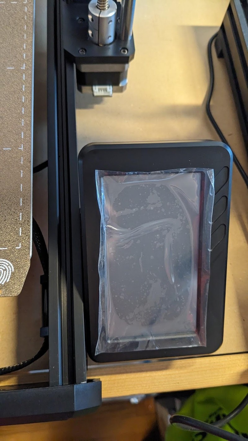
- Install the touchscreen bracket and slot in the touchscreen.
- Complete all electrical connections. All connectors are keyed so that they can only be connected one way.
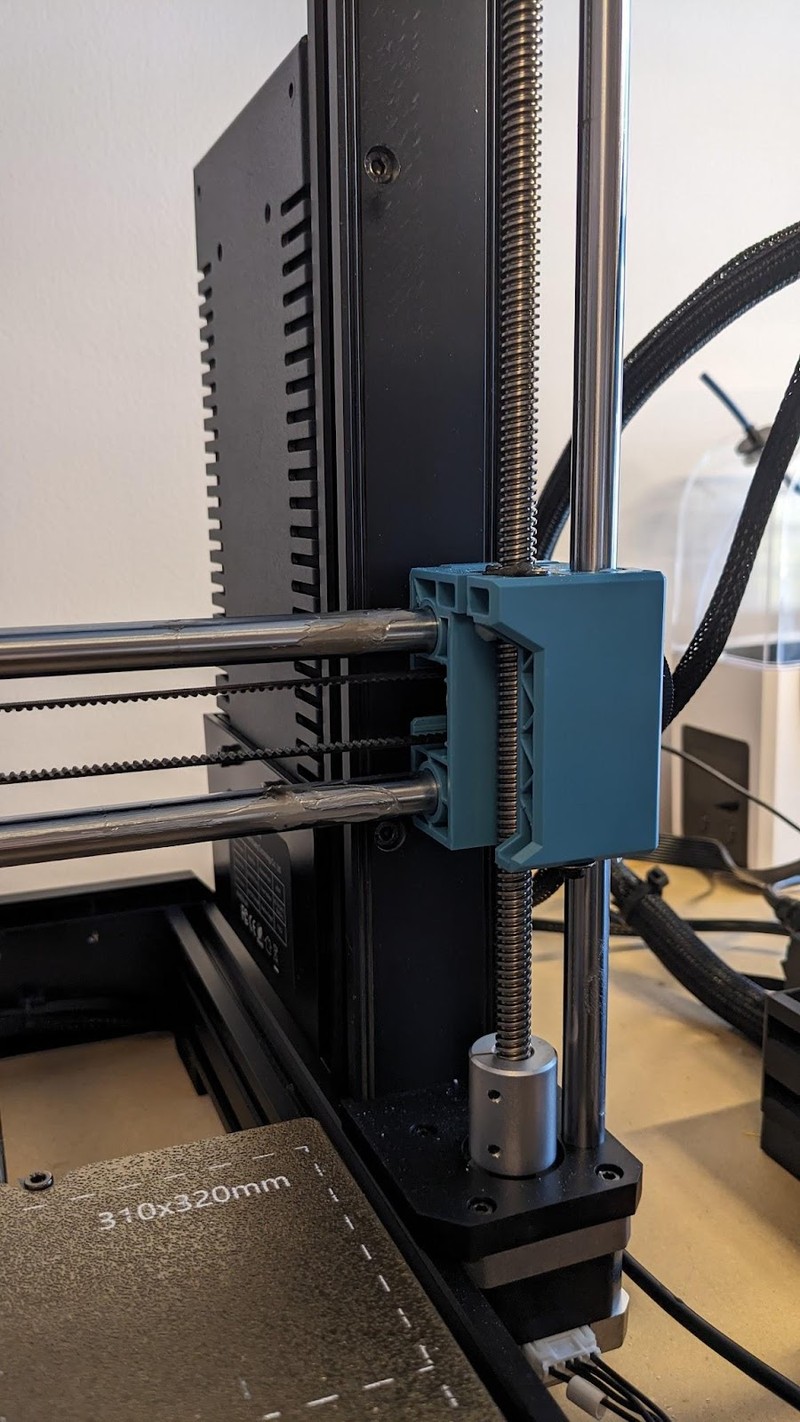
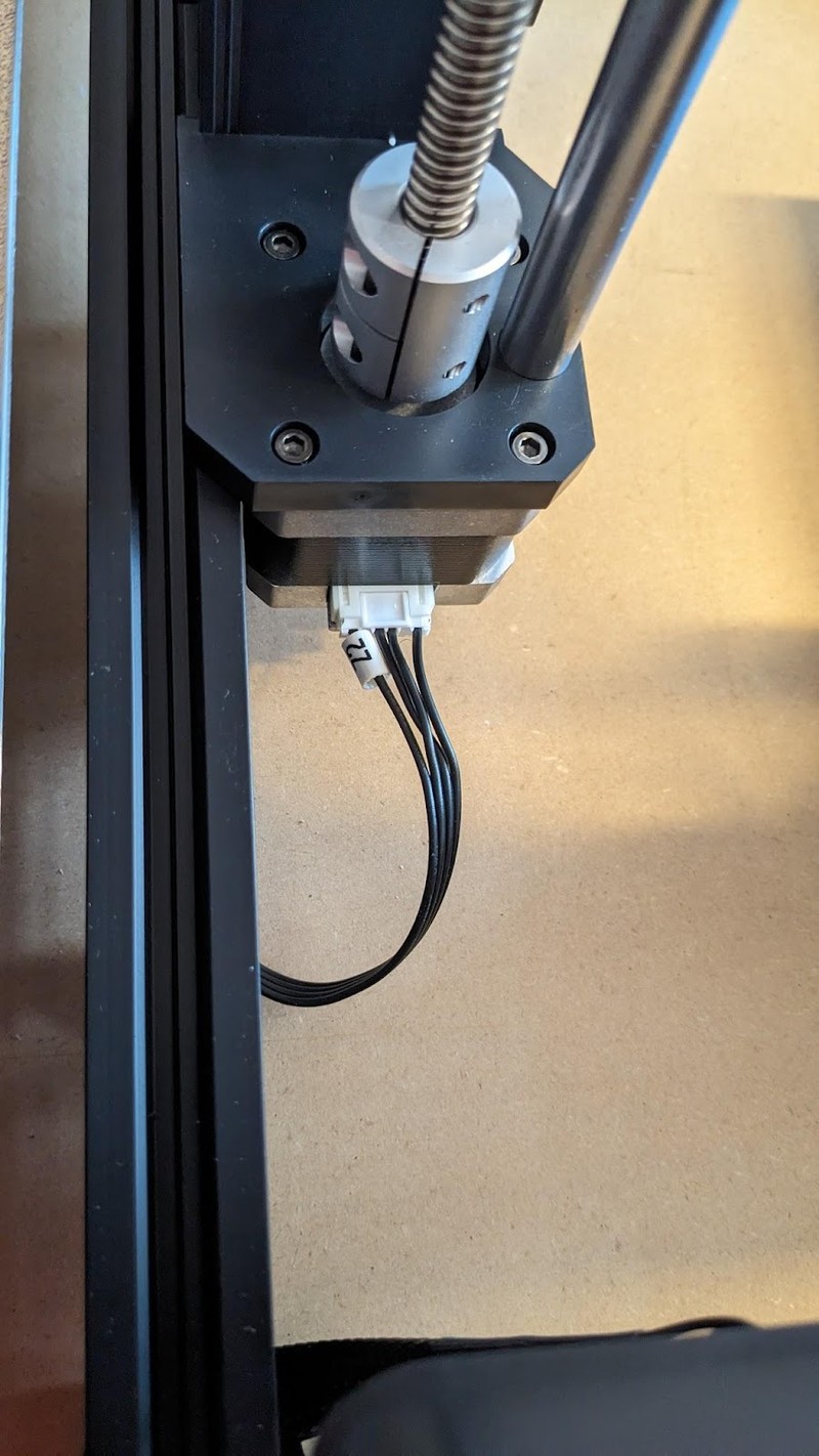
— the two Z axis stepper motors
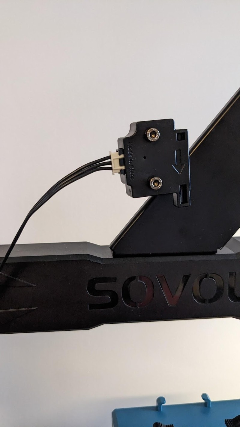
— the touchscreen
— the filament runout sensor at the bottom and top of the gantry
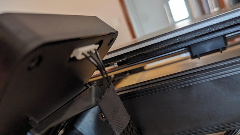
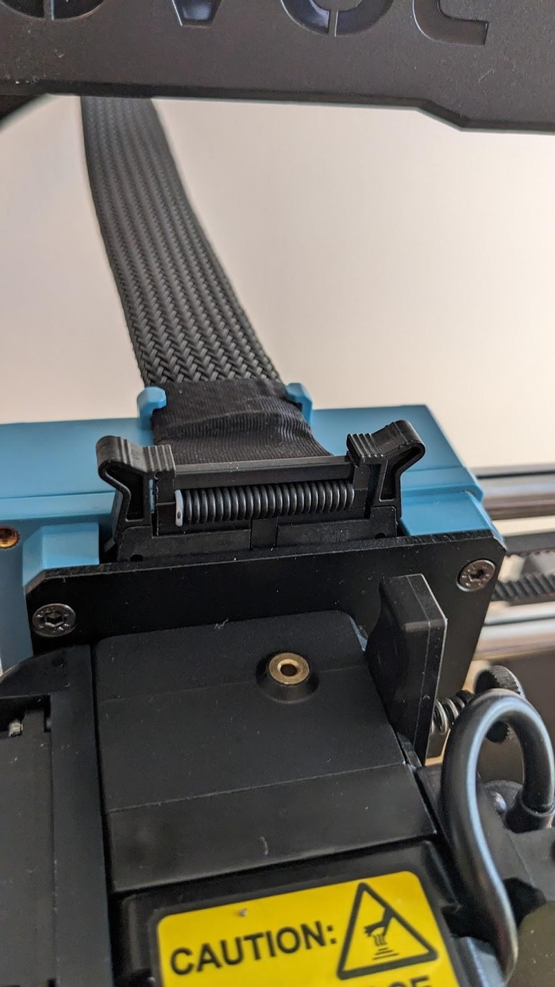
— the flat ribbon cable to the extruder. The extruder cable had to be folded a bit so that it could slot into the retainer.
— the Y axis (bed) stepper motor (not pictued)
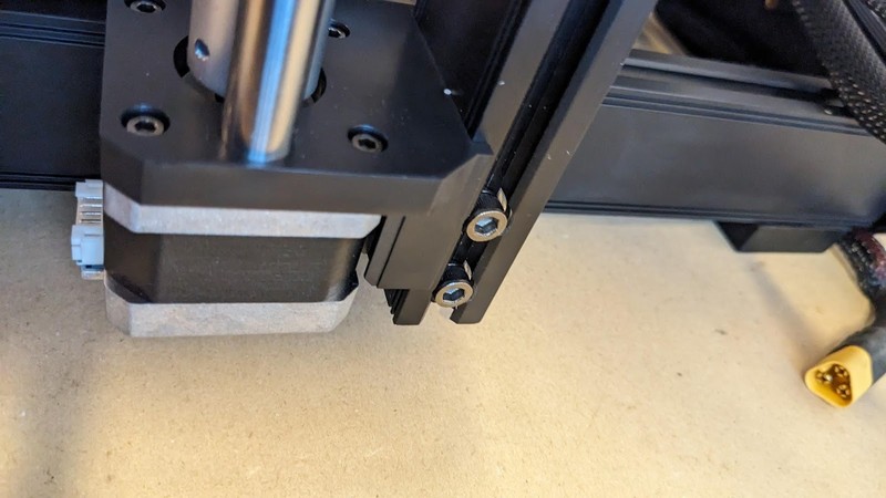
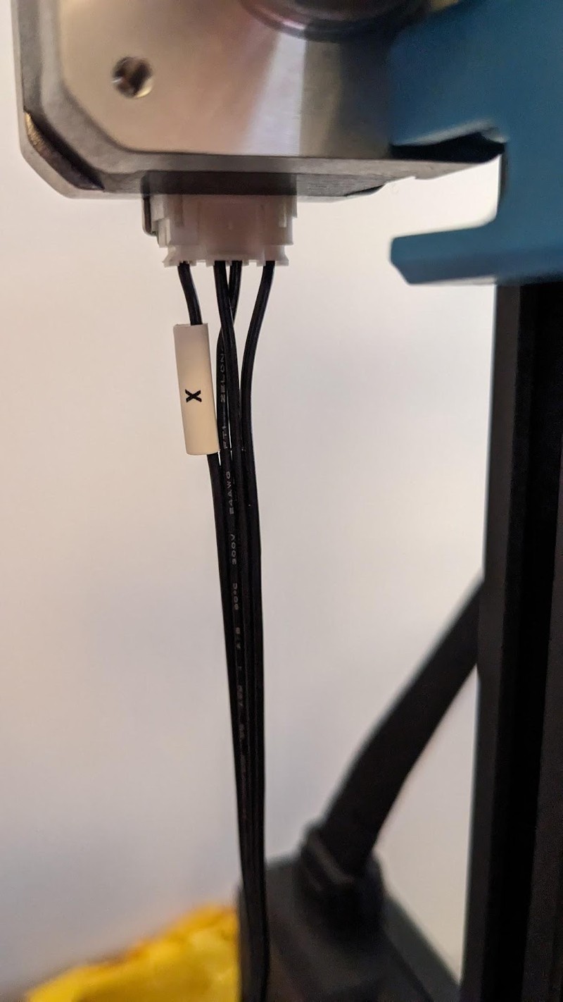
— the X axis stepper motor using its long cable
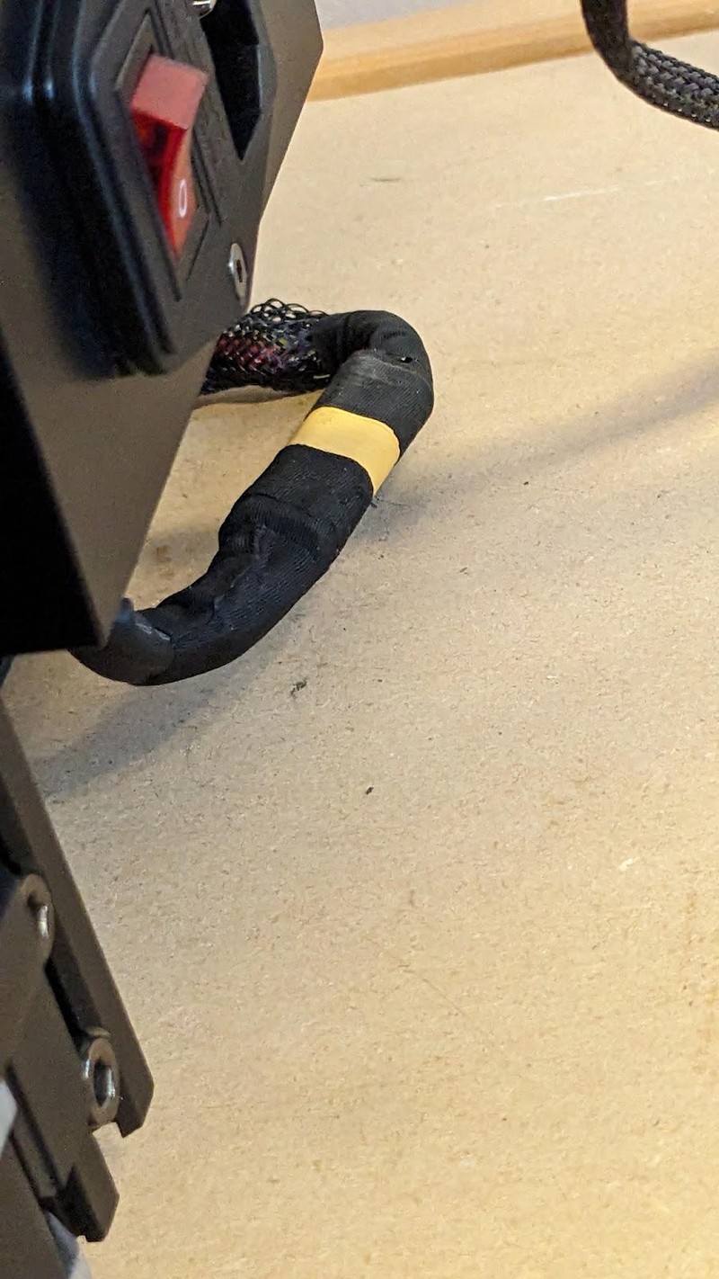
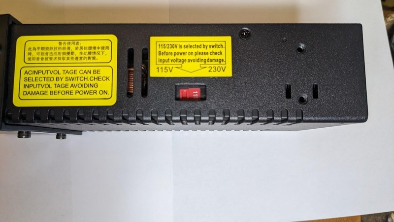
— the power supply. The power supply uses 3 conductor XT-60 connectors which can handle high current and lock together very securely. Then it was clipped into the extruder with locking tabs. Don’t forget to set the power supply voltage switch - it was set for 230V from the factory which would cause malfunctions on 115V power systems.
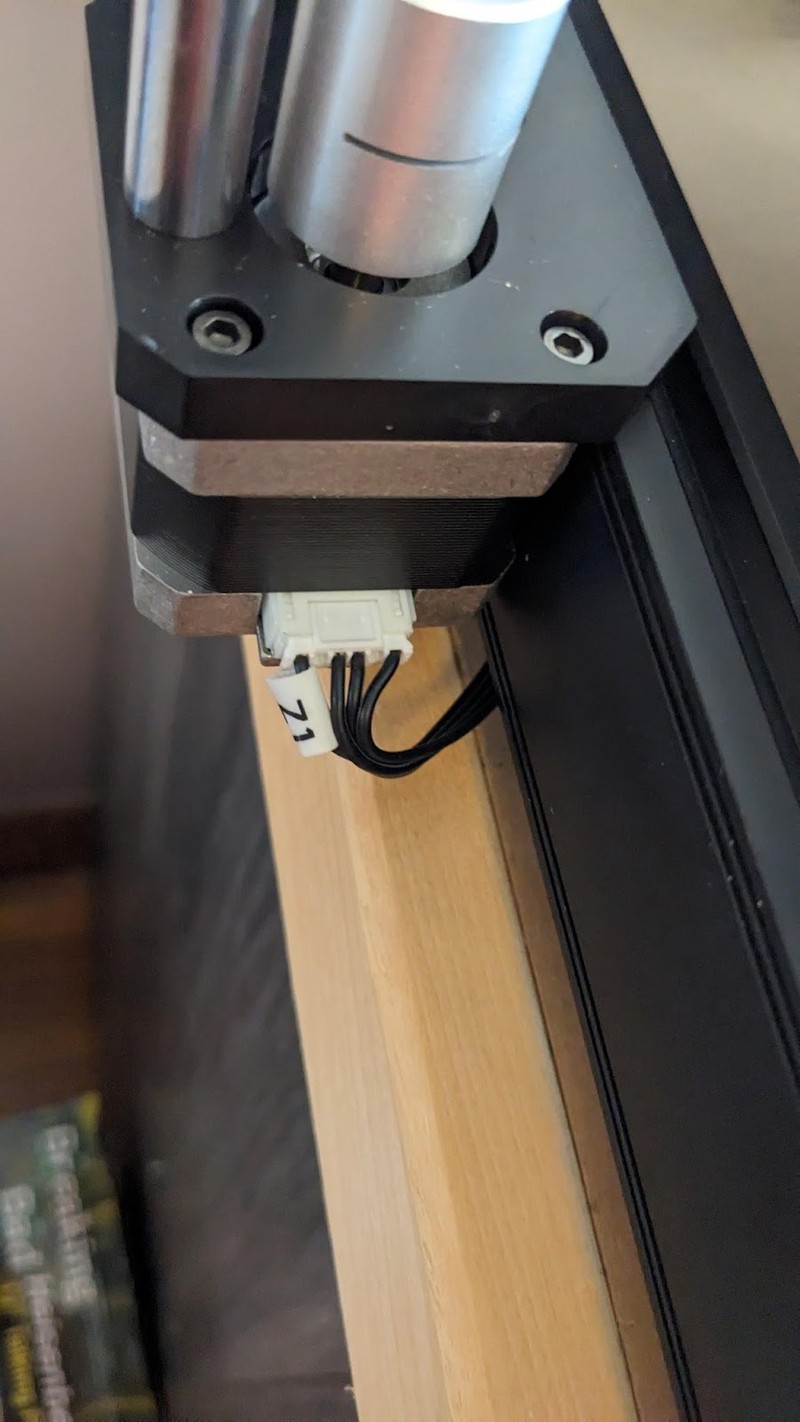
Z motor 1
The printer is now assembled! Learn more about the SV06 plus at the links below.